|
| Radial and axial flow from a slit type pintle injector for liquid rocket engine |
 |
| Spray from a slit type pintle injector for a liquid rocket engine. |
 |
| Spray quality of a pintle injector can be controlled by the differential pressure between two inlets. |

Its design is simple and fabrication can be finished within one week. Procedure for design and fabrication of a slit type injector for a liquid rocket engine is mentioned below. A slit type pintle injector can be designed with just 5 simple steps.
- STEP 1-Select the thrust and propellants of the rocket engine-5000N, RP1-LOX
- STEP 2 -Combustion chamber pressure – 15 Bar
- STEP 3- Fix the optimum mixture ratio of the rocket engine
- STEP 4- Find out the Flame temperature, molar mass, specific heat ratio and characteristic velocity of the exhaust gases in the rocket combustion chamber using NASA CEA application.
- STEP 5-Calculate the mass flow rate of fuel, oxidizer and the pintle injector exit area required to achieve this mass flow rate.
A pintle injector can be fabricated using the following procedure.
- Select the outer diameter of the pintle
- Select fuel centered or oxidizer centered configuration.
- Divide the circumference of the pintle into equal number of holes equidistant from each other.
- Divide the discharge area into the number of holes to be made on the pintle.
- Now the holes can be split into two rows, a primary row and a secondary row.
- Select the diameter of the holes and the distance between these holes.
- Outer diameter of the annular gap can be calculated by oxidizer discharge are=Pi(R*R-r*r), where r and R corresponds to inner and outer radius of the annular gap.
Table below shows the different parameters of a 5000N engine calculated using Pintle Design Software.
Pressure (Atm)
|
Optimum Mixture Ratio
|
C.F
|
Area of throat (mm2)
|
Mass flow rate Kg/s
|
Area of Fuel discharge(mm2)
|
Area of Oxidizer
discharge(mm2)
|
Annular gap (mm)
|
Pintle opening (mm)
|
10
|
2.11
|
1.27
|
39.21
|
2.19
|
46.01
|
81.22
|
0.7
|
1.29
|
15
|
2.15
|
1.36
|
24.39
|
2.04
|
42.2
|
76.27
|
0.65
|
1.21
|
20
|
2.17
|
1.42
|
17.53
|
1.95
|
40.09
|
73.12
|
0.61
|
1.16
|
25
|
2.2
|
1.46
|
13.62
|
1.89
|
38.49
|
71.17
|
0.59
|
1.13
|
30
|
2.21
|
1.5
|
11.1
|
1.87
|
37.86
|
70.32
|
0.58
|
1.11
|
- Let the outer diameter of pintle be 13.1 mm. So the circumference of the pintle is 41.15 mm
- We take fuel centered approach indicating fuel is supplied through the slit holes in the pintle.
- From the table above, area required for fuel discharge is 42.2 mm2. This area should be divided for two rows so each row gets 21.1 mm2.
- Now small holes totalling to an area of 21.1 mm2 should be separated equidistantly through out the circumference of the pintle.
- Select the diameter of the holes and the distance between these holes.The number of holes
possible=pintle circumference/(Single hole diameter+Distance between holes).
- let diameter be 0.55 mm and distance between holes be 1 mm. So number of holes possible is 27.22. If remainder comes, accommodate that remainder equally in the spacing between the holes. So 0.22/2 can be accommodated in spacing. So spacing between holes becomes 1.008mm.
- Now second row holes below the first row should be placed in such a way to fill the gap created by the first row of pintle holes. Just keep the second row holes in the centre of gap in primary row.
- Now annular gap for oxidizer discharge need to be fixed. Oxidizer discharge area is 76.27 mm2. The lesser the sheet thickness the more good will be the resulting spray. The annular gap area should be 76.27mm2. Radius of outer circle of the annular gap=square root of {(Oxidizer discharge are/Pi)+r*r}=8.196 mm. Annular gap=outside radius(R)-inside radius(r)=8.196-6.55=1.64 mm.
Material suitable for Slit type pintle injector is stainless steel(SS304) due to its strength and heat resistance.
- Buy one long bit of stainless steel having a damter of 60 mm or above as per the combustion chamber size.

3 parts of a slit type pintle injector, a base plate, pintle and an annular disc.
- Now drill four holes in the outer circumference for fastening.
- Cut the long bit into two equal pieces. One for attaching pintle and other for creating the annular gap.It is better to drill holes for bolts before cutting the metal to avoid mismatch of drilled holes.
- Take one bit, drill a hole in the center of bit and make a thread in the hole for the pintle to be screwed in. The other end of the bit is the inlet to the pintle.
- Take the other bit and drill an inside hole of diameter 16.392 mm to match the annular gap of 1.64 mm. Drill a suitable hole perpendicular to the circumference of the bit till it reaches the centre hole.This is the inlet for the annular gap flow.
- Now take a stainless tube pipe and turn it to 13.1 mm diameter in size.Or drill a hole inside another bit of necessary length and make the outer diameter 13.1 mm. One side of the pintle need a outside thread matching the inside thread of the first bit and the other end should be closed in the shape of a dome.
- Now use EDM machine to drill the 27 holes of 0.55 mm diameter holes in the circumference of the pintle.
- Screw in the pintle to the base bit, take the second bit and match it with the first bit holes and bolt it tight using stainless steel bolts.
- Connect the fuel and oxidizer to the respective inlets and pressurize the system using nitrogen gas cylinders.
- Open the tank valves and enjoy testing the injector at different conditions. You have made the same injector that is used in SpaceX Merline engines that power Falcon 9 rockets.

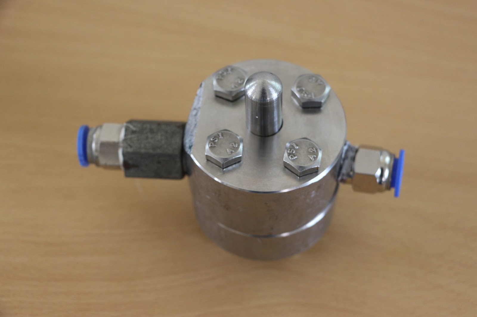
Assembled slit type pintle injector. Inlets to the annular discharge is given from left and right sides for even water discharge from the annular gap.

 |
| Making pintle in a lathe machine. |
 |
| Pintle and base plate after lathe operation. |
 |
| Slit type pintle screwed inside into the base plate. |